Saturday, February 21, 2009

Sample and Hold: Not just a random LFO

Amongst some keyboard players, sample and hold has become synonymous with a random LFO. Check out this video from Automatic Gainsay that shows how the ARP 2600 sample and hold works.


So it's only a random LFO when you feed it noise. Also, if you think your synth has one sample and hold, you might be wrong. In analog monosynths the keyboard CV is controlled by a sample and hold circuit fed by the keyboard. Remember that the keyboard itself isn't doing anything after a key is released but notes must continue (with duration controlled by Release). It's also used in conjunction with the portamento control. Polysynths like the Jupiter-6 have tons of sample and hold circuits for various CVs for each voice.

To see a simple sample and hold circuit and description, see "SAMPLING" here. The Rogue uses a variation of this.

The "In" is coming from the keyboard. It is the current key's voltage or open when no keys are played. C3 is the capacitor that gets charged and holds the keyboard voltage. It is also used with R13 to form a low pass filter for portamento a.k.a. glide. R12, R14, and R15 are there for protection since the CV in and out are connected to a jack on the back. Someone could inadvertently fry the op-amp by plugging in something they shouldn't.

Wednesday, February 11, 2009

2810: An ARP Odyssey part 2

Like the Moog examples, the ARP Odyssey keyboard current will go through the keyboard resistor string. However, if two notes are held down at the same time the current will bypass the resistors between the notes since they are shorted out by the buss.

Up to this point we've been concerned about the buss voltage, which is responsible for pitch CV. But what about the voltage supplied by the current source to the high end of the resistor string? Let's figure out what happens to that using the Odyssey as an example. When one note (or none) is held down the high end of the keyboard voltage is 3-I*Rall where I is the current and Rall is the resistance of all resistors in the chain. For the Odyssey it's 3-.00083*36*100 = 0 V. But if two keys are held down the resistors between them are shorted out. So the voltage is 3-I*(Rall-Rbetween). But since we know 3-I*Rall = 0, this simplifies to I*Rbetween. This is how the Odyssey gets it's duophonic capability.

This voltage I*Rbetween is the CV difference between the two notes. Remember a normal CV is still generated by the keyboard voltage buss and corresponding S+H circuit. At oscillator 2 this voltage can just be added to the normal pitch CV, giving a CV corresponding to the high note.

Tuesday, February 10, 2009

2810: An ARP Odyssey


Up to this point I've been talking about monophonic keyboard circuits. ARP figured out a clever way to cheat, making the synth duophonic without much extra. First let's figure out what the difference is between this circuit (from the later Odysseys) and the Moog versions.

I should first mention there is still a keyboard voltage buss not shown where the contacts make, uhhh contact just like the Moog examples. In this schematic the + power supply (arrow pointing up) is 15 V. R13 and R17 form a voltage divider between 15 V and ground. This gives 15*R13/(R13+R17) = 3 V at the + input of the op-amp. The voltage of the - input of the op-amp will be the same. So the "keyboard low" voltage is 3 V. How about the current? It is just the current flowing through R11 and R12. The current flowing into J2-6 (up through R11 and R12) is (15-3)/(R11//R12) where R11//R12 is the parallel resistance of R11 and R12. This gives 0.83 mA. Once again this is 1/12 V per note. There is a major difference though. The current is flowing into the "keyboard low" so the keys are decreasing in voltage as you move up the keyboard. The highest key (3 octaves up) is at 0 V.

It is pretty simple to invert this voltage later to get an increasing V/oct scale. Two questions come up first, is this high or low note priority? Since the "keyboard low" is held at a specific voltage, the buss voltage will only depend on the current supplied and the resistance up to the lowest note held. So this is still low note priority like the Moog examples. The second question is why make the keyboard voltage backwards in the first place? If you've been paying attention you've probably guessed it has something to do with being duophonic. That explanation will be the topic of the next post.

Sunday, February 8, 2009

Rogue vs. Prodigy

The Moog Rogue is similar to the Prodigy but came out a couple of years later. The keyboard current source circuit is almost except for a few differences.
  • The op-amp is a 353 instead of 4558. The 353 has JFET input stages. This means much smaller input and bias currents (more than 1000x smaller). However the input offset voltage is 2-3x higher.
  • There is no longer a resistor connected to the + input. I guessed that that resistor used the bias current to compensate for the input offset voltage. The smaller bias current means that won't work.
  • The resistor between the trimpot and - input is 130k instead of 301k 1%. This seems like a counter-intuitive change. The current can now be adjusted between 12/14.3-12/130 = 0.747 mA and 12/14.3+12/130 = 0.931 mA. This makes it harder to adjust the trimpot for the 0.833 mA. My theory on why this change was made is compatibility. According to various sources, the Micromoog originally had a pitch CV of 0.9V/oct that could not be adjusted. The Rogue allows for a range of 0.896-1.11 V/oct.

Saturday, February 7, 2009

Minimoogs do it discretely


How do Minimoogs do it? With discrete transistors. I've highlighted the keyboard resistor string and current source. Here are the differences between the Minimoog from the Prodigy:
  • The current source uses two BJTs instead of an op-amp.
  • There are 43 resistors instead of 31 because there are 44 keys instead of 32.
  • The resistors are 10 ohm instead of 100 ohm. This is because we are using discrete BJTs for the current source, which will give a smaller, less ideal, current source output resistance. This is overcome by making the load smaller.
  • The current needs to be 10x that of the Prodigy because of the smaller resistors.
The current shown on the schematic is 8.33 mA, which gives the 1/12 V for each key. Let's solve for this current using some quick and dirty approximations. We will assume the transistor base current is negligible and for both transistors Vbe = 0.7 V.
  1. R20 and R22 form a voltage divider between 10 V and ground. Vb of Q11 is 5 V.
  2. If Q11 Vbe is 0.7 V, then Q9 Vb is 4.3 V.
  3. If Q9 Vbe is 0.7 V, then Q9 Ve is 5 V.
  4. Q9 Ie is (10-5)/590 = 8.5 mA.
  5. The current source comes from Q9 Ic, which will be almost equal to Ie = 8.5 mA.
This is pretty close to 8.33 mA. Where did I go wrong? I assumed the Vbe of the transistors was the same. First of all, they aren't match and one is NPN, the other PNP. Second of all, The current through them is not equal, so the Vbe values will be different. The current through Q11 is about 4.3/1k = 4.3 mA. We found the current through Q9 is almost twice this. The Q9 Vbe will be about 18 mV greater than Q11 Vbe based on the Ebers-Moll BJT model (26 mV*ln(2)). Q9 Ve will be about 5.018 V. Q9 Ie will be (10-5.018)/590 = 8.44 mA. Now assume Q9 has a Beta of 160. Our current source will be 8.45*159/160 = 8.39 mA. Now we're less than 1% off from the expected 8.33 mA. That's close enough considering we have 1% resistors.

Tuesday, February 3, 2009

Prodigy Keyboard Current Source

Let's look at the keyboard current source used in the Prodigy. The lowest key is connected to the "0.00V" inverting (-) op amp terminal. The highest key is connected to the "2.66V" op amp output. In case you don't remember, here are the rules for ideal op amps with negative feedback: There is no current going into the + or - inputs. The voltage difference between the + and - is so small we can assume the two voltages are equal. The output does whatever it can to make this happen.

Let's figure out the current.
  1. First off, no current into the + input, therefore no voltage drop across R84.
  2. The voltage of the + input is 0.
  3. The voltage of the - input must also be 0.
  4. No current into - input so the current going through the keyboard resistor string is equal to the current going through R83 and R179 by Kirchoff's Current Law.

There's a trimpot so I will solve for current at both extremes of the trimpot position. First when the pot wiper is at +12V, I = 12/14.3k-12/301k = 0.799 mA. At -12V I = 12/14.3k+12/301k = 0.879 mA. Between those positions, the trimpot can be adjusted to our magic 0.833 mA to give 1/12 V across each 100 ohm resistor.

A question I have looking at this: Why is the high note keyboard voltage 2.66V? We have 32 keys, but 31 resistors between them. V = 31*1/12 = 2.58 V. Someone made a math error and figured 32*1/12 = 2.66 V.

Another question I have looking at this: What is R84 for? Why not connect the + input directly to ground? In our ideal op amp world it works but notice the op amp is a 4558. In the not-so-ideal world this op amp uses bipolar transitors which have a bias current coming out of the + input. So the + input is a little bit above ground in our example. From the datasheet the input bias current is 50 nA. The + input voltage is 50 nA*18k = 0.9 mV. Also from the datasheet the input offset voltage is 1 mV. That means the - input is held very close to ground (roughly 0.9-1 = 0.1 mV) because of R84.

R83 and R179 are 1% to ensure the proper current range. C22 is presumably there for stability while still allowing the output voltage to change quickly enough when new notes are played.

There are plenty more where that came from. Check back for the Rogue, Minimoog, and more.

Sunday, February 1, 2009

The Prodigy Keyboard Circuit part 2

So we determined a voltage source to the keyboard circuit won't work. Here is a current source used instead. The lowest key is still connected to ground. What should be the current I? Each resistor is 100 ohm and should have 1/12 V across it. By Ohms Law I = V/R = 1/(12*100) = .833 mA. What happens when two keys are held down at the same time? Like the previous example with the voltage source, the current will bypass the resistors between the two keys. To solve for 
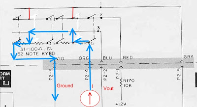
Vout, we see the point on the far left is grounded. Vout will just be I*(Resistance from ground to the lowest key held down). Pressing higher keys won't do anything to Vout. This is the reason for low note priority.

It would be just as easy to make a keyboard with high note priority. The highest note could be held at 2.58 V. The current source would be connected the opposite way to the lowest note to sink current. Making a last-note-priority keyboard would be much more difficult to make. Figuring out the last note played really requires digital logic, so it wasn't until the introduction of microprocessors in synths that last note priority became common. The SH-101 and Pro-One come to mind. The SH-101 has a last-note/low-note priority switch so the synth shredders of the day could still use their Moog soloing techniques.

Now that we've established why we need a current source, we can ask why 100 ohm 1% resistors are used. (It looks like .1% on this scan of the schematic. Other scans definitely have 1% and I'm fairly certain .1% aren't manufactured). The 1% is easy. Our ears are very sensitive to pitch. If a note is 5% (5 cents) out of tune, it will be noticeable. Why 100 ohm? Consider this. If the resistors were large, say 100k, we could save power. The power used by the keyboard when no notes are played is V^2/R. We can't change V because we are using 1V/oct. But if we switched from 100 ohm to 100k ohm, it would require 1/1000 the power. What's the problem?

We are using a current source. In a perfect world it wouldn't matter, but real current sources have an output resistance. It is a large resistance in parallel with the current source. If we are driving a load with small resistance, this output resistance won't matter. But if the load is comparable to the output resistance, the current source will start misbehaving.